Probes and Signals
Probe and Signal Rails
The Production Line Tool allows interaction with several test probe and signal rails :
Power Rails
Digital Probes
Analog Probes
Serial interfaces (UART, SWD, JTAG, CAN)
Test Probe and Signal Rails
rail |
Description |
PLT-200A |
PLT-300A |
|---|---|---|---|
1.8V DUT Power Rail |
n/a |
✓ |
|
3.3V DUT Power Rail |
✓ |
✓ |
|
5V DUT Power Rail |
✓ |
✓ |
|
Variable DUT Power Rail |
✓ 2..12V |
✓ 2..24V |
|
CAN (H) |
✓ |
✓ |
|
CAN (L) |
✓ |
✓ |
|
Clock Signal #0 |
✓ |
✓ |
|
Clock Signal #1 |
✓ |
✓ |
|
Direct Analog Test Probe #0 |
✓ MUX0/1 |
✓ MUX0/1 |
|
: |
: |
✓ MUX0/1 |
✓ MUX0/1 |
Direct Analog Test Probe #6 |
✓ MUX0/1 |
✓ MUX0/1 |
|
Direct Analog Test Probe #7 |
✓ |
✓ |
|
: |
: |
✓ |
✓ |
Direct Analog Test Probe #12 |
✓ |
✓ |
|
Direct Digital Test Probe #0 |
✓ MUX2/3 |
✓ MUX2/3 |
|
: |
: |
✓ MUX2/3 |
✓ MUX2/3 |
Direct Digital Test Probe #8 |
✓ MUX2/3 |
✓ MUX2/3 |
|
Direct Digital Test Probe #9 |
✓ |
✓ |
|
: |
: |
✓ |
✓ |
Direct Digital Test Probe #12 |
✓ |
✓ |
|
Direct Digital Test Probe #13 |
✓ UART/TP |
✓ |
|
Direct Digital Test Probe #14 |
✓ UART/TP |
✓ |
|
PLT System Ground |
✓ |
✓ |
|
DUT GND #1 |
✓ |
✓ |
|
DUT GND #2 |
✓ |
✓ |
|
DUT GND #3 |
✓ |
✓ |
|
DUT GND #4 |
✓ |
✓ |
|
JTAG TCK |
✓ |
✓ |
|
JTAG TDI |
✓ |
✓ |
|
JTAG TDO |
✓ |
✓ |
|
JTAG TMS |
✓ |
✓ |
|
JTAG TRST |
✓ |
✓ |
|
3.3V Power Rail |
✓ |
✓ |
|
test voltage |
✓ |
✓ |
|
Routed Analog Test Probe #0 |
✓ MUX0/1 |
✓ MUX0/1 |
|
: |
: |
✓ MUX0/1 |
✓ MUX0/1 |
Routed Analog Test Probe #31 |
✓ MUX0/1 |
✓ MUX0/1 |
|
Routed Digital Test Probe #0 |
✓ |
✓ |
|
: |
: |
✓ |
✓ |
Routed Digital Test Probe #127 |
✓ |
✓ |
|
reference voltage |
✓ |
✓ |
|
SWD nRST |
✓ |
✓ |
|
SWD Clock |
✓ |
✓ |
|
SWD IO |
✓ |
✓ |
|
SWD SWO |
✓ |
✓ |
|
3.3V Power Rail |
✓ |
✓ |
|
UART #0 CTS |
✓ |
✓ |
|
UART #0 RTS |
✓ |
✓ |
|
UART #0 RxD |
✓ |
✓ |
|
UART #0 TxD |
✓ |
✓ |
|
3.3V Power Rail |
✓ |
✓ |
|
UART #1 CTS |
✓ |
✓ |
|
UART #1 RTS |
✓ |
✓ |
|
UART #1 RxD |
✓ |
✓ |
|
UART #1 TxD |
✓ |
✓ |
|
3.3V Power Rail |
✓ |
✓ |
|
VARVOUT after 1/3 divider |
✓ |
✓ |
Ground Rails
rail |
Description |
PLT-200A |
PLT-300A |
|---|---|---|---|
DUT GND #1 |
✓ |
✓ |
|
DUT GND #2 |
✓ |
✓ |
|
DUT GND #3 |
✓ |
✓ |
|
DUT GND #4 |
✓ |
✓ |
|
PLT System Ground |
✓ |
✓ |
Test Plan Commands
Power Rails
rail |
Description |
PLT-200A |
PLT-300A |
|---|---|---|---|
1.8V DUT Power Rail |
n/a |
✓ |
|
3.3V DUT Power Rail |
✓ |
✓ |
|
5V DUT Power Rail |
✓ |
✓ |
|
3.3V Power Rail |
✓ |
✓ |
|
3.3V Power Rail |
✓ |
✓ |
|
3.3V Power Rail |
✓ |
✓ |
|
2..24V DUT Power Rail |
✓ |
✓ |
Test Plan Commands
Analog Test Probes
rail |
Description |
MUX0 |
MUX1 |
MUX2 |
MUX3 |
|---|---|---|---|---|---|
Direct Analog Test Probe #0 |
✓ |
✓ |
nc |
nc |
|
: |
: |
✓ |
✓ |
nc |
nc |
Direct Analog Test Probe #6 |
✓ |
✓ |
nc |
nc |
|
Direct Analog Test Probe #7 |
nc |
nc |
nc |
nc |
|
: |
: |
nc |
nc |
nc |
nc |
Direct Analog Test Probe #12 |
nc |
nc |
nc |
nc |
|
Routed Analog Test Probe #0 (ADG0 Bank) |
✓ |
✓ |
nc |
nc |
|
: |
: |
✓ |
✓ |
nc |
nc |
Routed Analog Test Probe #15 (ADG0 Bank) |
✓ |
✓ |
nc |
nc |
|
Routed Analog Test Probe #16 (ADG1 Bank) |
✓ |
✓ |
nc |
nc |
|
: |
: |
✓ |
✓ |
nc |
nc |
Routed Analog Test Probe #31 (ADG1 Bank) |
✓ |
✓ |
nc |
nc |
DATP
rail |
Description |
MUX0 |
MUX1 |
MUX2 |
MUX3 |
|---|---|---|---|---|---|
Direct Analog Test Probe #0 |
✓ |
✓ |
nc |
nc |
|
: |
: |
✓ |
✓ |
nc |
nc |
Direct Analog Test Probe #6 |
✓ |
✓ |
nc |
nc |
|
Direct Analog Test Probe #7 |
nc |
nc |
nc |
nc |
|
: |
: |
nc |
nc |
nc |
nc |
Direct Analog Test Probe #12 |
nc |
nc |
nc |
nc |
13 Direct Analog Test Probes (DATP00…DATP12)
Input-only
Connected directly from PPC to PLT
DATP00…DATP06are hooked up to the built-in DMM of the PLT-300A, for precise measurements at voltages up to 100V.DATP00…DATP06can be switched to the MUX0 and MUX1 channels for shorting, impedance or voltage measurementsDATP00…DATP12are connected directly to ADCs, allowing differential voltage measurements, and voltage measurements against PLT system ground.
Test Plan Commands
RATP
rail |
Description |
MUX0 |
MUX1 |
MUX2 |
MUX3 |
|---|---|---|---|---|---|
Routed Analog Test Probe #0 (ADG0 Bank) |
✓ |
✓ |
nc |
nc |
|
: |
: |
✓ |
✓ |
nc |
nc |
Routed Analog Test Probe #15 (ADG0 Bank) |
✓ |
✓ |
nc |
nc |
|
Routed Analog Test Probe #16 (ADG1 Bank) |
✓ |
✓ |
nc |
nc |
|
: |
: |
✓ |
✓ |
nc |
nc |
Routed Analog Test Probe #31 (ADG1 Bank) |
✓ |
✓ |
nc |
nc |
32 Routed Analog Test Probes (RATP00…RATP31)
Input-only
Connected from PPC to PLT through an analog multiplexer on the PPC
Only one routed analog test probe from a given ADG bank can be routed at the same time.
RATP00…RATP15are part of the “ADG0 Bank”RATP16…RATP31are part of the “ADG1 Bank”RATPxxpins can be routed to MUX0 and MUX1 channels for shorting, impedance or voltage measurements
Test Plan Commands
Digital Test Probes
rail |
Description |
MUX0 |
MUX1 |
MUX2 |
MUX3 |
|---|---|---|---|---|---|
Direct Digital Test Probe #0 |
nc |
nc |
✓ |
✓ |
|
: |
: |
nc |
nc |
✓ |
✓ |
Direct Digital Test Probe #8 |
nc |
nc |
✓ |
✓ |
|
Direct Digital Test Probe #9 |
nc |
nc |
nc |
nc |
|
: |
: |
nc |
nc |
nc |
nc |
Direct Digital Test Probe #14 |
nc |
nc |
nc |
nc |
|
Routed Digital Test Probe #0 |
nc |
nc |
nc |
nc |
|
: |
: |
nc |
nc |
nc |
nc |
Routed Digital Test Probe #127 |
nc |
nc |
nc |
nc |
See also
DDTP
rail |
Description |
MUX0 |
MUX1 |
MUX2 |
MUX3 |
|---|---|---|---|---|---|
Direct Digital Test Probe #0 |
nc |
nc |
✓ |
✓ |
|
: |
: |
nc |
nc |
✓ |
✓ |
Direct Digital Test Probe #8 |
nc |
nc |
✓ |
✓ |
|
Direct Digital Test Probe #9 |
nc |
nc |
nc |
nc |
|
: |
: |
nc |
nc |
nc |
nc |
Direct Digital Test Probe #14 |
nc |
nc |
nc |
nc |
15 Direct Digital Test Probes (DDTP00…DDTP14)
Connected directly from PPC to PLT
DDTP00…DDTP08 are hooked up to the built-in DMM of the PLT-300A, for precise measurements at voltages up to 100V.
DDTP00…DDTP08 can be switched to the MUX2 and MUX3 channels for shorting
Can be configured as inputs (no pull-up) or outputs (low or high)
Can sense logic state for probes that are configured as inputs
Test Plan Commands
RDTP
rail |
Description |
MUX0 |
MUX1 |
MUX2 |
MUX3 |
|---|---|---|---|---|---|
Routed Digital Test Probe #0 |
nc |
nc |
nc |
nc |
|
: |
: |
nc |
nc |
nc |
nc |
Routed Digital Test Probe #127 |
nc |
nc |
nc |
nc |
128 Routed Digital Test Probes (RDTP00…RDTP127)
Connected from PPC to PLT through a multiplexer on the PPC
Can be configured as inputs (with or without pull-up) or outputs (low or high)
Can sense logic state for probes that are configured as inputs
Test Plan Commands
Clock Signals
rail |
Description |
MUX0 |
MUX1 |
MUX2 |
MUX3 |
|---|---|---|---|---|---|
Clock Signal #0 |
nc |
nc |
nc |
nc |
|
Clock Signal #1 |
nc |
nc |
nc |
nc |
CLK
2 clock signal rails (CLK0, CLK1)
Test Plan Commands
Serial Interfaces
PLT-300A |
Rear |
|---|---|
|
HD78 |
|
HD78 |
|
HD78 |
|
HD78 |
|
HD78 |
|
HD78 |
|
HD78 |
|
HD78 |
|
HD78; SWD |
|
HD78; SWD |
|
HD78; SWD |
|
HD78; SWD |
|
HD78 |
|
HD78 |
|
HD78 |
|
HD78 |
|
HD78 |
|
HD78; CAN |
|
HD78; CAN |
UART
PLT-300A |
Rear |
|---|---|
|
HD78 |
|
HD78 |
|
HD78 |
|
HD78 |
|
HD78 |
|
HD78 |
|
HD78 |
|
HD78 |
2x UART interfaces (UART0, UART1)
Test Plan Commands
SWD
PLT-300A |
Rear |
|---|---|
|
HD78; SWD |
|
HD78; SWD |
|
HD78; SWD |
|
HD78; SWD |
1x SWD interface
Test Plan Commands
JTAG
PLT-300A |
Rear |
|---|---|
|
HD78 |
|
HD78 |
|
HD78 |
|
HD78 |
|
HD78 |
1x JTAG interface
Test Plan Commands
CAN
PLT-300A |
Rear |
|---|---|
|
HD78; CAN |
|
HD78; CAN |
1x CAN interface
Test Plan Commands
Signal Routing
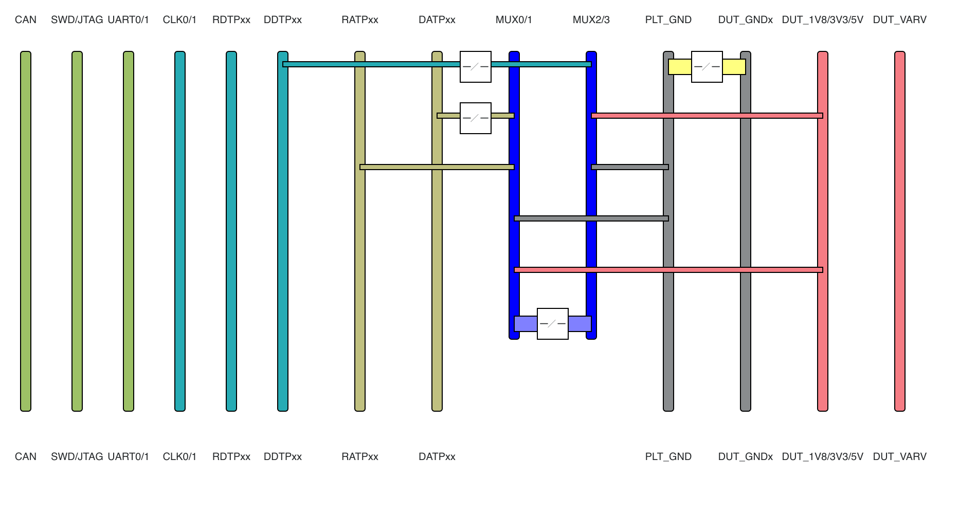
PLT-300A Signal Routing
See also
Switchboard
rail |
Description |
MUX0 |
MUX1 |
MUX2 |
MUX3 |
|---|---|---|---|---|---|
1.8V DUT Power Rail |
✓ |
✓ |
✓ |
✓ |
|
3.3V DUT Power Rail |
✓ |
✓ |
✓ |
✓ |
|
5V DUT Power Rail |
✓ |
✓ |
✓ |
✓ |
|
Direct Analog Test Probe #0 |
✓ |
✓ |
nc |
nc |
|
: |
: |
✓ |
✓ |
nc |
nc |
Direct Analog Test Probe #6 |
✓ |
✓ |
nc |
nc |
|
Direct Digital Test Probe #0 |
nc |
nc |
✓ |
✓ |
|
: |
: |
nc |
nc |
✓ |
✓ |
Direct Digital Test Probe #8 |
nc |
nc |
✓ |
✓ |
|
PLT System Ground |
✓ |
✓ |
✓ |
✓ |
|
test voltage |
✓ |
✓ |
✓ |
✓ |
|
Routed Analog Test Probe #0 |
✓ |
✓ |
nc |
nc |
|
: |
: |
✓ |
✓ |
nc |
nc |
Routed Analog Test Probe #31 |
✓ |
✓ |
nc |
nc |
|
reference voltage |
✓ |
✓ |
✓ |
✓ |
Test Plan Commands